Bus Corridor Operational Improvement with Intelligent Transportation System based on Autonomous Guidance and Precision Docking
Está matéria tem 0 comentários.Bus Corridor Operational Improvement with
Intelligent Transportation System based on
Autonomous Guidance and Precision Docking
Leopoldo R. Yoshioka, Claudio L. Marte, Mauricio Micoski, Renato D. Costa, Caio Fontana,
Cledson A. Sakurai, Jose R. Cardoso
Abstract— It is important to bring to Urban Transportation, in
specific of medium capacity, solutions that allow it to increase
efficiency. This article shows functionalities associated to Intelligent
Transportation Systems that can contribute to the increase in
efficiency of Urban Collective Transportation. In particularly, the
automation of a conventional bus by way of Autonomous Guidance
Technology, which consists of magnetic sensing, computational
intelligence and electro-mechanical actuator. The automation of the
lateral guidance provides for docking maneuvers with better
precision at the stops, in addition to allowing the vehicle to travel on
narrow routes quickly and safely. One application of this technology
is presented in Expresso Tiradentes bus corridor in São Paulo, where
the achieved results demonstrate improvements in the efficiency of
bus operations.
I. INTRODUCTION
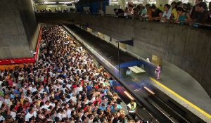
N the medium and large cities it is notorious the increasing
difficulty in displacing its citizens, which entails in an
increasing loss of mobility. This is felt by longer times
necessary for displacement, transfers and waits [1]. In part,
this is a result of the competition among modes of
transportation in utilizing a shared network.
In the rail mode, it is noticed a lesser case of competition
because different types of services can share the same track, as
well as the existence of railway junctions with traffic lights
that restrict flow and increase travel time [2]. But, both,
(different types of services and railway junctions with traffic
lights) are uncommon.
Now on the road mode exists a sharper competition among
vehicles responsible for Collective Transportation (High
Occupancy Vehicle) and Individual Transportation. This
competition enhances the occurrences of congestions. These
imply in a longer wait time at intersections and on
This work was supported in part by the FINEP – Brazilian Agency of
Inovation.
L. R. Yoshioka, C.L. Marte and J.R. Cardoso are with the University of
Sao Paulo (USP) (+55-11-3091-5578; e-mail: leopoldo.yoshioka@usp.br)
C. Fontana and C.A.Sakurai are with Federal University of Sao Paulo
(UNIFESP) (e-mail: caio.fernando@unifesp.br)
M. Micoski and R.D. Costa are with Compsis Computadores e Sistemas,
São Jose dos Campos, Brazil (renato.costa@compsis.com.br).
displacement, as well as, a decrease on the Collective
Transportation quality of services [3].
The attempt of resolving these difficulties (longer travel
times and congestion) by increasing the infrastructure of the
routes and allowing a larger capacity offered to vehicles of
Individual Transportation has been exhaustively put into
practice, not only in Brazil, but also in other countries. And
this is a path that runs out in short time, having a consensus
that priority should be given to Collective Transportation in
relation to Individual Transportation.
Therefore there is a necessity that migration from Individual
Transportation to Collective Transportation should be
stimulated. And, for that to occur in a Collective
Transportation that associates larger capacity and
differentiated services, that is of better quality, it should be
sought.
In Brazil it is common the offer of Collective Transportation
Systems of low capacity and frequently of lower quality.
When enquired, the population declares a strong preference for
systems of high capacity, like the metro. However, it is
necessary a high level of investment and a long time of
implementation, what makes its quick dissemination unviable.
Obviously, when it comes to meet a high/medium demand
with solutions of low capacity, the result is a provision of a
service of low quality.
Brazil lives in a phase where transportation solutions of
medium capacity may meet, at least in part, the desire of the
population to enjoy a service of better quality. Because of
that, it is positive the experiences of the Monorail in São Paulo
and Bus Express Corridors . i.e. Bus Rapid Transit (BRT)
under implementation in most cities hosting the World Cup in
2014 [4].
BRT is a mode of public transportation on tires, fast and
flexible, that combines stations, vehicles, services, routes and
intelligent transportation systems (ITS) elements in an
integrated system with a strong positive identity that evokes a
unique image.
This choice for the BRT is based on the volume of
investment required [5], time of implementation and the
possibility of incremental improvements during operation.
What can be difficult to observe on systems above rails, in
more critical points or of bigger impact, evolving over time
until it reaches its fullness [6].
The BRT has potential to revolutionize the current situation,
presenting itself as one of the most recommended options for
transportation systems of medium capacity, because it is
widely favored for the cost-benefit relations and time versus
complexity of implementation.
For the BRT to reach the highest levels of efficiency (lower
cost and greater reliability), safety and comfort – for users of
Collective Transportation it is fundamental the utilization of
the advances in the Information and Communication
Technology (ICT) area. The BRT is a concept that presents
itself in a clear manner to the evolutions of Collective
Transportation services can with the combined application of
ITS technologies and more efficient use of urban space.
II. INTELLIGENT TRANSPORTATION SYSTEM FOR PUBLIC
TRANSPORTATION
In the Urban Collective Public Transportation (UCPT)
exists the necessity to explore the potential of utilization of
ITS technologies in the BRT systems [7], hereinafter referred
to as ITS4BRT.
Recent studies show that ITS functions could improve BRT
systems [4] [8] [9]. In the following we present a summary of
concepts of ITS4BRT, including main Actors and relevant ITS
Functionalities.
Actors
We show in Fig 1 a hierarchical representation of the actors
involved in the ITS4BRT. One cans see below a summarized
description:
1. Conductor: operates a licensed vehicle;
2. Operational Controller: is responsible for monitoring
and controlling the hourly schedule of the UCPT route.
The activities include: monitoring, controlling,
measurements of congestion, route modifications and
provision of public transportation;
3. Operator: is responsible for the management of fleets
conditioned to rules defined by Transportation Regulatory
Agency;
4. Passenger: represents an individual (or group) not
part of the crew, inside of a vehicle, when the trip is
taking place;
5. User: represents all human entities that utilize,
directly or indirectly, the transportation services. In
accordance with the moment and situation, this actor can
be a pedestrian, Traveler, Passenger, Conductor, or any
other that benefits with provide services;
6. Traveler: represents any individual that utilizes
transportation services.
A. Intelligent Transportation Functionalities for Bus Rapid
Transit System (ITS4BRT)
As shown in Fig. 2 we can organize main service groups of
the ITS4BRT into seven groups (or service domains), which
are described in the following:
1. Planning and Programming: detailed in the next
section;
2. Management: detailed in the next section;
3. Electronic Ticketing (Fare): set of services responsible
for the commercialization of credits, from the issuance,
passing by distribution, validation e effective collection
(billing) to the compensation (“clearing”), allowing the
integration between different modes of transportation;
4. Information to Users: services: set of services
responsible for distributing, in an extensive manner, up to
date and effective static and dynamics information about
the transportation network and services to Users;
5. Prevention and Safety: set of services responsible to
provide greater safety to Traveler/ Passenger/ Conductor,
in the aspect to avoid action by a third parties (“security”),
as to prevent against operational risks (“safety”);
6. Multimodal Coordination: set of services responsible
for the coordination between transportation and traffic
system, aiming at improving the intermodal transfer and
prioritize Public Transportation at signalized
intersections; and
7. Infrastructure: focuses on the continuity of the
operation, maintaining the infrastructure and auxiliary
services, as electric energy supply, telecommunications,
data processing and others.
III. PLANNING, PROGRAMMING, MANAGEMENT AND CRITICAL
AUTONOMOUS SYSTEM
These groups of services involve definition and
establishment of services standards and quality indicators. This
set of services also addresses the Critical Autonomous System

that includes the Precision Docking and Autonomous
Guidance features.
A. Planning
Functionality utilized to establish service quality and
define resources and infrastructure necessary. In the
service standards and quality of the services established,
for example: degree of accessibility, levels of comfort,
levels of service integration, maximum wait times
(minimum frequency and commercial speed), quality/performance indicators e levels of prevention.
And, as far as resources and infrastructure are defined, for
example: bus line and route planning, and service offers.
B. Programming
Based on Planning and in function of the resources
available, the Service Programming of the UCPT takes
place, searching for a better relation between supply and
demand, with the issuance of Operational Service Orders
(daily schedule), detailing, for example: allocation of
vehicles per route, frequency, travel time, itineraries,
hourly schedules (grid) and allocation of human resources
(Conductor).
C. Management
This is a group of functionalities that performs
monitoring and control in real time of parameters and
events of the UCPT system, through the comparison with
the programmed, intervening, when necessary, aiming to
suit the operation to the defined standards. In the
following we describe the functions that compose this
group.
c1) Measurements
Functions associated to collection, processing and
visualization of information (parameters) around the
vehicle and of the infrastructure (stations, terminals and
routes), necessary to the operation. Are examples of
information shipped in the BRT vehicles: monitoring of
the state (safety devices, opening/closing of doors) and
measurements of continuous variables (positioning,
speed, acceleration, occupation and functions of
engine/vehicle structure). Examples of information
associated to infrastructure (stations, terminals and
routes): User/Traveler count (at terminals and platforms)
and on the routes – count and identification of vehicles,
measurement of speed, red light crossing and
unwarranted occupation.
Functions referred to the capacity of generating the main
inputs involved in the service provision of the UCPT,
aiming to manage the Maintenance and Control and the
Quality of Services Provided. As far as the functionality
of following maintenance and control of input, like
examples: information about fuel consumption and
conservation, ware of parts and accessories. To measure
the quality of services will be necessary information that
allow it to evaluate the conduction of the vehicle, seeking
to capture dada that reflect traffic safety, Passenger
comfort and the form of integration between vehicle and
the Conductor.
c3) Management of Services Provided
Functions that allow it to monitor the trip performance of
the UCPT and perform the Management Operation,
monitoring and controlling, in real time, the elements of
the UCPT’s system, with the purpose to provide an
operation within the parameters pre-established in
Planning and Programming the operation. These
parameters refer to the conditions that the system should
operate and that are subject to interference of the
processes that could be originated for various factors like:
climatic conditions, events, works and actions of the
Conductor among others. Are examples of functions:
maintain the regularity and reliability of services;
confront the scheduled planed (programmed) versus the
scheduled executed (actual); adjust dynamically the
supply and demand and adjust the operation to a situation
not expected, considering the resources available.
D. Critical Autonomous System
This is group of functionalities to assist, in an automatic
or semi-automatic way, operations that need a greater
degree of safety, precision or speed, aiming at the
optimization of the operation. The objective of this group
is to turn the operational performance of the BRTs close
to the systems on rail. Following are described the
functions that compose this group.
d1) Control of Routes and Stations Doors
Function referred to the capacity of automatic opening
and closing of doors of the stations and monitoring of the
corridor routs of the UCPT.
As for Automatic Door Opening Control, this could
contribute to increment safety, the commercial speed and
the operational flow, maintaining the synchronization of
the door opening at the stations with the UCPT vehicles.
d2) Monitoring of the use of corridor routes
Function referred to monitoring of the use and to
reprimand the utilization of the BRT lanes by nonauthorized
vehicles.
d3) Precision Docking
This function is utilized in the alignment of the vehicle
with the platform, at the stops or stations, for passenger
embarking and disembarking operations. In these
operations, in accordance with the characteristics of the
systems, it could exist the necessity to perform it with
more agility and precision, aiming to eliminate variations
from the different levels of ability of the Conductor.
d4) Autonomous Guidance
This function allows, in isolated and straight routes, a
more precise and secures driving, without the necessity of intervention by the Conductor, except in emergency
situations. The application of this functionality can
provide an increase of the commercial speed.
IV. AUTONOMOUS GUIDANCE AND PRECISION DOCKING
The purpose of the Autonomous Guidance System (AGS)
is to replace the action of the conductor in the steering
control of the vehicle. It allows the bus to perform approach
and docking maneuvers at the stops with a lot more

precision and quickness. The vehicle could also travel in
straight routes quickly and safely. It consists of sensor,
signals processors, on-board computer and actuator. It can
be installed in any type of vehicle. It is capable of automatic
positioning and alignment of the vehicle on the road, with
precision and reliability.
As it is shown in the photos sequence in Fig. 3, the vehicle
can operate in the manual mode or automatically being that the
conductor continues present, still being responsible for the
control of the speed, stops and departures. The set of photos in
Fig.4 shows details of the precision docking maneuvers at a
stop.
The autonomous guidance system is composed of four main
segments: Position Sensing; Signal Processing; Guidance
Control; and Steering Wheel Actuator. In the following you
will find a brief description for each of these segments:
A. Position Sensing
It is a fundamental part of the AGS, since, based on the
information obtained by the position sensing is what
determines the lateral positioning of the vehicle in relation to
the road. There are basically five types of reference of
positioning applicable for AGS, including magnetic lane, lane
marking on the route (optic), Differential Global Positioning
System (DGPS), electromagnetic and the magnetic marker
[14].

Evaluation the applicability for the BRT, from each of the
reference types based on criteria of safety, robustness,
flexibility, durability, and cost of implementation arrived at the
conclusion that the two more adequate types are the magnetic
marker and the optic [15]. In this article it will be addressed
only the sensing by magnetic marker. Fig. 5 illustrates a
magnetic marker used in Expresso Tiradentes Corridor (São
Paulo).
B. Signal Processing
It is responsible for extracting information of the lateral
deviation from the signals captured by the sensing system.
Through the signal processing it is determined the position
of the profile peak of the magnetic field generated by the
magnet. From this information the lateral deviation of the
vehicle is calculated [16] [17]. Fig. 6 illustrates the
tridimensional view of the magnetic field profile generated by
a magnetic track. It can be observed that the peaks follow the
polarity (north or South) of the magnets, which can be utilized
to code geometry information of the route.
C.
C. Guidance Control
The guidance control is responsible for the maintenance of the correct lateral position of the vehicle on the route. From
the information of the lateral deviation of the vehicle obtained
through the signal processing, the control generates the
command for the actuator to apply the right steering angle to
correct the lateral deviation of the vehicle [18]. Fig. 7 shows a
representation of the vehicle utilizing the bicycle model [19].
In the following we describe some of the components
utilized in guidance control.
c1) Kalman Filter
The state of the vehicle is composed of the following
variables:
• x: lateral distance measured from the track to the
vehicle, in the direction perpendicular to the body
of the vehicle;
• y: position of the vehicle measured along the route;
• Ψ: angle between the body of the vehicle and the
track.
• α: steering of the front wheel, which is the angle
between the body of the bus and the direction to
where the front wheel is pointed;
• ρ: curvature of the reference to be followed. The
curvature is defined with the variation in the angle
of the tangent to the reference in relation to the
traveled distance.
When the magnetic sensor is used, the variables read are
x, y, Δα and ρ (the value of ρ is obtained from the desing
of the track and from the position measurement in which
the vehicle is found) and the Kalman filter is used to
estimate the values of x, α and Ψ [20] [21].
c2) State of the Vehicle Estimator:
The State Estimator reads the information form the
sensors, applies it to the Kalman filter and decides how to
use the results. One important decision of this module is
define if the actual state is trustworthy of not. In the
magnetic track case, the approximation between the
estimate and the state actually measured is used in this
decision.
c3) Control Algorithm:
The function of a Control Algorithm is to calculate the
steering that should be applied to cancel the lateral
deviation at a certain point ahead. When the reference
comes from a optic sensor is necessary to consider two
differences in relation to the use of the magnetic sensor:

the separation between samples and use of the curvature.
In the case of the magnetic sensor, the separation between
the samples is given by the distance between the magnets,
usually of 2 meters. As the speed of the vehicle varies,
the time between samples also varies, which brings

stability problems during high speeds. The use of the
curvature of the reference depends of the system being
capable of determining with precision in which point of
the track it is found. In the case of magnetic sensors, this
is done by the creation of binary codes based on the
polarity of the magnets installed. Between the codes, the
simple counting of the magnets detected provides one
information of position. With the position information,
the law of control can take into account the actual
curvature and of the segment ahead, anticipating the
steering at the entrance of curves. Fig. 8 shows the block
diagram of the guidance control system.
c4)Steering Wheel Actuator
The actuator is an electro-mechanical component that has
the function of transforming the output of the guidance
control system in triggering the steering wheel system, in
order to provide adequate steering of the directional
wheels of the vehicle, which are necessary to produce the
correction of the lateral deviation of the vehicle. It is
composed of controller, motor and mechanic coupling
with the steering system of the vehicle. The controller is
responsible for the communication with the guidance
computer that processes the guidance algorithm. The
engine in conjunction with the mechanic coupling
produces the mechanic movement necessary for the
triggering of the steering system of the vehicle. The block
diagram in Fig. 9 shows components of the wheel steering
actuator.
At each 50 milliseconds the guidance computer calculates
a new angular position assumed by the steering bar. This
information is passed by Controller Area Network (CAN)
for the engine controller. The controller commands the
engine in a closed loop, that is, it commands electrically
the position of the axle and reads, through an internal
sensor, if the axle reached the desired position. This
causes that angular position of the axle follows with great
precision the values determined by the Guidance’s
Central Processing Unit (CPU). The axle of the engine is coupled mechanically to reduction box, which amplifies
the momentum of 2Nm (servomotor capacity) to 20Nm
on the steering bar. This configuration was sufficient to
control the vehicle steering in all situations tested in real
condition in the bus corridor. The exit axle of the reducer
is connected to the clutch, which is the element of control
of the engine coupling to the steering bar. The clutch is
controlled electronically by the Auto/Manual button on
the driver panel. When the system is in Automatic mode,

the clutch transfers the movement of the exit axle of the
reducer to the steering bar. When the system is in Manual
mode, the clutch decouples both axles, and the steering
bar turns freely in relation to the exit of the reduction
box. As illustrated in Fig.9, the clutch is connected to the
steering bar by way of a belt coupled to a pulley installed
on the exit axle of the clutch and other installed on the
steering bar.
V. EXPERIMENTAL RESULTS
The graphs (a) and (b) in Fig.11 shows the radiuses of the
curves from the route and the respective lateral deviation of
the vehicle (in relation of the magnetic track) of a segment of
750 meters of the Tiradentes Express between the Mercado
and Pedro II Stations.
It should be noted that autonomous guidance given
following operational precisions:
• Guidance Precision at the stops: 1.0 cm;
• Guidance Precision throughout the route;
This result creates the following perceptiveness for the Bus
Corridor operational improvements:
1. Reduction of passenger boarding and deboarding
time;
2. Increase in accessibility for users with disabilities,
children and the elderly;
3. Possibility of eliminating access ramps for
wheelchairs;
4. Possibility of operation on straight routes, enabling
the implementation of exclusive routes in urban centers;
5. Cost reduction of the corridor construction. It is
estimated that the road width could be reduced from
3.50 to 2.90 meters.
6. Time reduction in the bus approach and exit at the
stops.
7. Increase on the passenger comfort based on the standardization of the vehicle’s path along the route.
8. Driver’s stress reduction, which with the automatic
guidance can concentrate on the acceleration and
breaking control.

VI. CONCLUSION
Through the ITS4BRT when the denominated Critical
Autonomous System, more specifically the Docking Precision
and Autonomous Guidance functions, implemented on the Expresso Tiradentes bus corridor in São Paulo, it was possible
obtain an operational improvement of the BRT. As shown:
lateral deviation, on the docking maneuver at the stops, less
than one centimeter and lateral precision guidance, throughout
the route, less than five centimeters. In addition to the
performance improvement, the magnetic sensing alternative
was chosen based, among other criteria, of a smaller
investment necessary for implementation and maintenance.
VII. ACKNOWLEDGEMENTS
The authors wish to thank the FINEP (Brazilian Innovation
Agency) for partial support of the study. Also, wish to thanks
the São Paulo Transporte S/A (São Paulo City Transportation
Authority) and COMPSIS Computadores e Sistemas Ind. Com.
Ltda, for the opportunity to conduct this research.
VIII. REFERENCES
[1] V.R. Vuchic, Urban Transit – Systems and Technology, John Wiley &
Sons, 2008.
[2] M. Brons, M. Givoni, P. Rietveld, Acess to railway stations and its
potential in increasing rail use, Transport Research, Part A: Policy and
Practice, vol. 43, issue 2, pp. 136-149. 2008.
[3] R. Cervero, Vehicle trip reduction impacts transit-oriented housing,
Journal of Public Transportation, vol. 11, No. 3. 2008.
[4] L. C. Marte, et al, Preliminary study of ITS functions applied to BRT
(ITS4BRT). Public Transport Magazine, National Association of Public
Transport (ANTP, Brazil), Nº 130, Jan 2012.
[5] J. Lerner, Comparative evaluation of the public urban transportation
modes, NTU, National Association of Urban Transportation (Brazil).
Brasília, 92 p., 2009.
[6] ANTP – National Association for Public Transportation (Brazil) –
Intelligent Transportation Systems – Technical Notes Series – Vol. 8,
Sao Paulo, 2012.
[7] ITDP, Institute for Transportation & Development Policy, Bus Rapid
Transit Planning Guide, USA, 2007.
[8] APTA, American Public Transportation Association. Standards
Development Program Recommended Pratice: Implementing BRT
Intelligent Transportation Systems. 2010.
[9] AUSTROROADS, Association of Australian and New Zealand Road
Transport and Traffic Authorities, Defining Applicability of
International Standards for Intelligent Transport Systems (ITS). APR338/
10. 2010.
[10] H.S. Levinson, Bus Rapid Transit on City Streets – How Does It
Works? In Second Urban Street Symposium, Anaheim, CA. 2003.
[11] ISO/TR 14813-2, Transport information and control systems –
Reference model architectures for TICS sector – Part 2: Core TICS
reference architecture. ISO International Organization for Standization,
2000.
[12] US National Intelligent Transportation Systems Architecture, version
7.0, Department of Transit (DoT), 2012.
[13] ITS Architecture for Canada Release 2.0
[14] S.E. Shiladover et al, Lane Assist Systems for Bus Rapid Transit,
Volume I : Technology Assessment, noCalifornia PATH Research
Report, University of California at Berkeley, November 2007.
[15] W. Zhang et al, Lane Assist Systems for Bus Rapid Transit: Needs and
Requirements, California PATH Research Report, University of
California at Berkeley, November 2007.
[16] C.Y. Chan, A System Review of Magnetic Sensing System for Ground
Vehicle Control and Guidance. California Path Program, Berkeley,
2002.
[17] M. Micoski, L.R. Yoshioka, Lateral displacement calculation
algorithm for a Magnetic Guidance System. In SAE Technical Paper,
2007-01-288, 2007.
[18] M. Micoski, L.R. Yoshioka, Automatic Pilot for Buses: a Brasilian
Reality, SAE Technical Paper, 2008-36-088, 2008.
[19] Ackermann et al, Linear and nonlinear controller design for robust
automatic steering, in: Proceedings of the IEEE Transactions on
Control Systems Technology, vol. 3, No. 1, 1995.
[20] K. Ogata, Modern Control Engineering, Prentice Hall, New Jersey,
2008.
[21] H. Ouarda, The proposed 3 D Navigation Approch of an Autonomous
Mobile Robot, Latest Trends on Circuits, Systems and Signals,
WSEAS Conference, CORFU, 2010.
Leopoldo Rideki Yoshioka born in São Paulo, Brazil in 1961. He received
electronic engineer degree from Aeronautical Institute of Technology (ITA),
Brazil, on 1984. He obtained master and PhD degree from Tokyo Institute of
Technology (Tokyo Tech), Japan, on 1988 and 1991.
He is currently a Professor of the Department of Electronic Systems
Engineering at the University of São Paulo (USP), Brazil. His current
research interests include embedded systems applied to the Intelligent
Transportation Systems (ITS) and Autonomous Vehicles. He is a member of
ITS Committee at the National Association of Public Transport (ANTP).
Claudio Luiz Marte born in São Paulo, Brazil, in 1963. In 1985 he
completed his Degree at the Federal University of São Carlos [UFSC] and in
1988 completed Electrical Engineering (Electronic) at
the Polytechnic School of the University of Sao Paulo [USP]. In 1994 he
presented his Master of Science (MSc) and in 2000 he defended his Doctorate
in Engineering (DE) thesis in Electrical Engineering (Digital Systems) at
EPUSP.
He is currently a Professor of the Department of Transport Engineering
(PTR) of EPUSP. His current research interests are: Moving Objects applied
in ITS – Intelligent Transport Systems, Electronic Fee Collection (EFC),
Advanced Public Transportation Services (APTS) and Advanced Traffic
Management Services (ATMS). He is a member of ITS Brazil and ITS
Committee of the National Association of Public Transport (ANTP).
Maurico Micoski born in Paramá, Brazil, in 1968. He received Electronic
Engineer degree from Aeronautical Institute of Technology (ITA), Brazil, on
1991. He obtained master degree in Electronic Engineering from ITA in 2006.
He is currently a Senior System Engineer in Compsis Computadores e
Sistemas, São Jose dos Campos, SP, Brazil.
Renato Duarte Costa born in Sabará, Minas Gerais, Brazil, in 1955. He
received Electronic Engineer degree from Aeronautical Institute of
Technology (ITA), Brazil, on 1977. He obtained Master degree in Electronic
Engineering from ITA in 1982 and MBA degree in Enterprise Management
from Funcação Getulio Vargas (FGV) in 2000.
He is currently Director at Compsis Computadores e Sistemas, São Jose
dos Campos, SP, Brazil.
Cledson Akio Sakurai born in São Paulo, Brazil, in 1972. He received the
engineer degree from Faculdade de Engenharia Industrial on 1995, Master
and PhD degree from Escola Politécnica of Universidade de SãoPaulo on
2004 and 2010.
He is currently, professor on Universidade Federal de São Paulo in
Electrical Engineering. His current research interests include smart city, smart
grid and telecommunications. He is a member of ASSESSPRO-SP (Software
Association of São Paulo) and member on technical council of technological
park in Santos.
Caio Fernando Fontana born in Botucatu, Brazil. He received the business
administration degree from Faculdade de Administração de Empresas de
Araçatuba on 1988, Master and PhD degree from Escola Politécnica of
Universidade de SãoPaulo on 2004 and 2009.
He is currently, on Universidade Federal de São Paulo in Business
Administration and Logistic. His current research interests include smart city,
logistic and transport. He is a revisor of FAPESP (Funding Agency of São
Paulo).
Jose Roberto Cardoso born in São Paulo, in 1951. He graduated in
Electrical Engineering in 1974 from Polytechnic School at University of São
Paulo (EPUSP). Obtained the master’s and doctor degree in Electrical
Engineering also from EPUSP. Between 1987 and 1988 conducted
postdoctoral studies at the Laboratoire d’ Electrotechnique Grenoble , France.
He is currently, Dean of the Polytechnic School at University of São Paulo.
His field of interest has been the Electromagnetism . The research developed
by him are centered on topics such as finite element analysis,
electromagnetism , grounding , electrical machinery and permanent magnets .
He was was coordinator of Continuing Education in Engineering ( PBUH )
for eight years – from 1998 to 2006 ; founder of the Brazilian Society of
Electromagnetism (SBMAG ), and Head of Engineering Department of
Electrical Energy and Automation ( PEA / EPUSP ) 2002-2006 . Currently,
he is responsible for coordination of the Laboratory of Applied
Electromagnetics (LMAG), which he founded in 1988 , and the coordination
of the Council of Technological Engineers Union of São Paulo (SEESP) .
Deixe um comentário